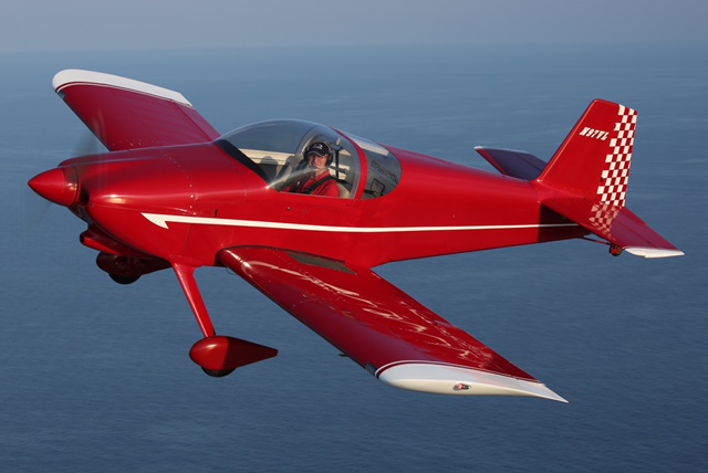
Drano's finished RV-6
Project
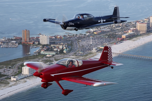
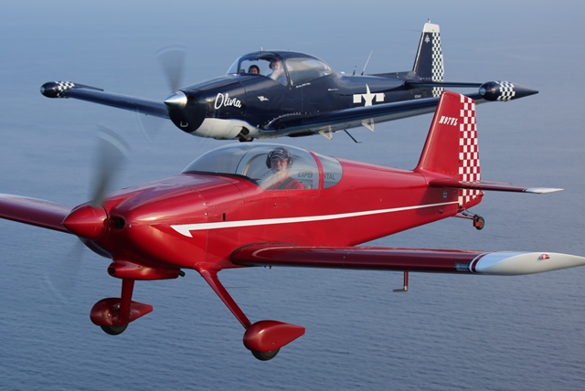
In Formation with
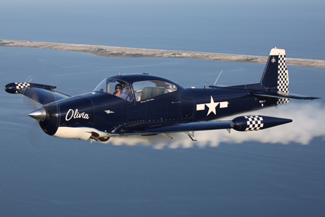
Tanner Matheny's Navion
AND
His Zenith CH 750 Project
Photo's buy Antonio
Gemma More, a flight instructor in the USN with a website focused on stories of
local aviators.
Go to www.photo01aviation.com
and check it out or email him at photo01bravo@gmail.com
A Note From Drano...
Tanner and I met up with Antonio at Ferguson to do some formation and photography work. They had a Cessna 172 with the right passenger door removed. Antonio was in a special harness and leaned out of the door as he snapped away. During our one hour flight, he said he took 3000 pictures. We had a ball, it was the most fun I have had in an airplane in a long time and I now have the pictures to show for it.
Drano’s Zenith CH 750 Project
In February of 2023, our EAA chapter received the gracious donation of a Zenith CH 750 project. It had been completed through a large portion of the fuselage, tail section, and wings. As the saying goes, “90% complete, 90% yet to go.” Our chapter decided to take silent bids for the project with highest bidder taking it home. I was casually searching for another airplane build project and had looked at half a dozen different projects none of which stirred my soul. I wasn’t in a hurry but I had enjoyed a flight in a Zenith 750 with a friend and thought what the heck, I’ll throw in a bid and see what happens.
On the 21st of March, 2023, two things happened…..one I will mention, the other is the focus of this project story. The first is that my youngest grand daughter was born. Her name is Eleanor “Norrie” Cook and if I ever decide to put a name on the side of the plane it will be hers. The second, as you probably already guessed, is that I was notified that I had won the bid and the project would be transferred to me. Thus this story begins.
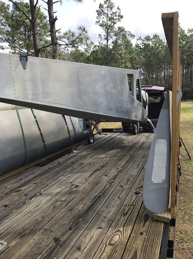
Drano’s Zenith CH 750 Project
loaded and ready for transport.
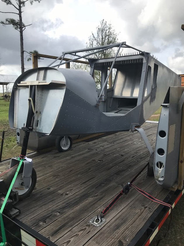
The two pictures above are of the project as our Chapter received it on the 24th of February 2023. Several of our members turned out to load and haul off the 750 project. The original builder had done us a huge favor by temporarily mounting “wheel barrow” wheels which allowed us to move it and load it easily. Things were looking up.
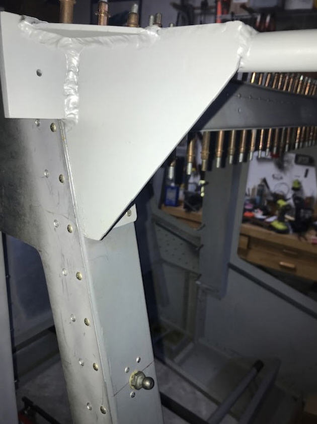
Much of the plane had been built by following plans and there were several departures from plans such as the picture above. You are looking at the rear wing mount that was fabricated with five different pieces of metal welded together. The plans called for a mount made of a single piece of metal. I have no doubt you could have hung the rear spar of a heavy transport on this fabrication but, like almost all departures from plans, changes seem to cascade into other sections quickly. Zenith did not make a door system that could be installed with this rear wing mount nor could any of the doors be modified to fit with this mount. Most of it had to be cut and ground away but there was still plenty of heft left in the mount when I was done.
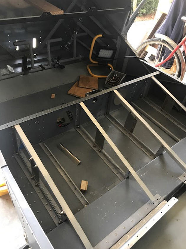
Another departure from the plans was the original builders intent to use seats from a Cessna 150 instead of the seat arrangement Zenith uses. The layout of their design as they modified it was very well thought out and well done but when I started to look at the weight difference between the Cessna seat structure compared to the Zenith plans, it was well worth the investment of labor to go as close as possible to the original plans and lighten the weight. It wasn’t as easy as just removing and replacing, there were many work arounds that had to happen and it took me a long time to get them done.
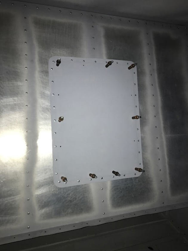
I decided to make an inspection hole in the rear bulkhead which is a departure decision that I made. IF one is to make an inspection hole, one might as well make it big enough to be able to work through.
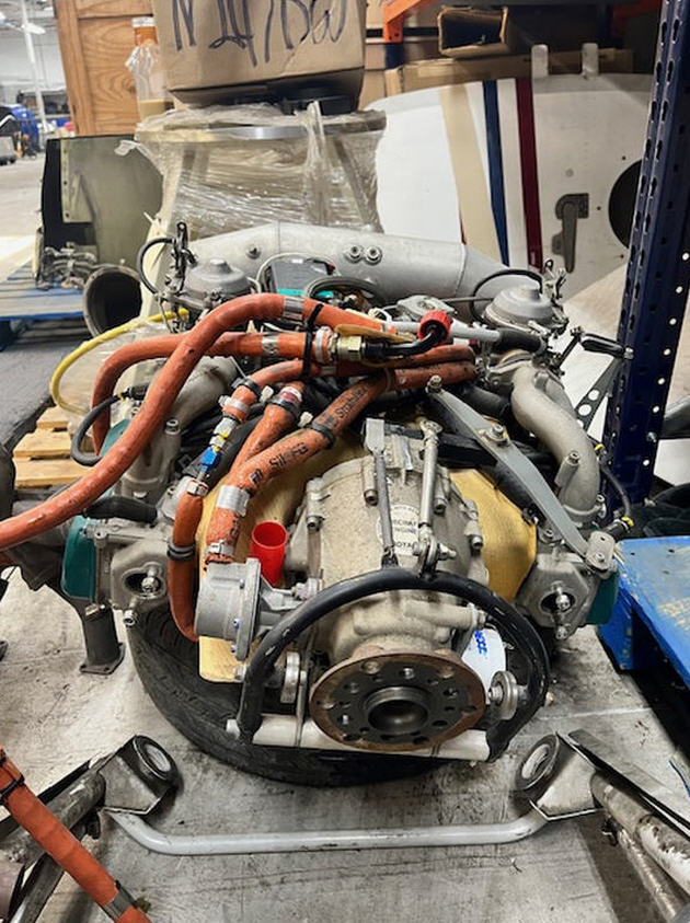
Early in any building project, you have to decide what engine you will use. Firewall and engine mounting considerations are driven by what “horse” is up front. I decided on a Rotax 912 ULS for a combination of reasons which included price, hp to weight, availability, and recommendations. I found the engine above at an aircraft salvage yard. It was an insurance sale off a powered sail plane that had been in a hangar that collapsed during a hurricane. The Sail plane was destroyed but no damage to the engine. It had roughly 400 hours it, all the logs, and was clean. My neighbor’s kids thought it looked like an octopus because of all the hoses on top. The plumbing of these engines is significant and will be the subject of comments later in the report.
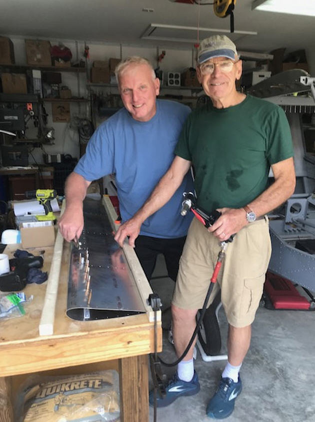
The CH 750 is a bit unique in that it has a flying rudder and flaperons. These had to be built. There are some projects that require five hands. If you have a friend help and hold your tongue just right, you can usually get er done.
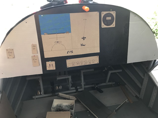
I toyed a little bit with cockpit panel design and here is an early card board-pin it where you think you want it attempt. I have made significant changes from this picture but the approach works well if you want to sit in the project and day dream about flying it. One decision I have made is to go with the IPad approach you see here only most likely it will be centered in the panel. Again, lots to be done and more to come as epiphanies occur.
This picture could be considered a great example of OCD. Ultimately, I wanted to have position and strobe lights. I fell into a great deal on a used set of AEROLEDs to mount on the wing tips. Zenith makes a wing cap made of fiberglass that has a flat spot for mounting wing tip lights but my wing tips were all metal without any mounting base. Furthermore, the wing tips have a 45 degree taper so to have my AEROLEDs on the wing tips, I had to build a base that would accommodate them. What you are looking at is a 45 degree base made of wood, covered in fiberglass, that will bolt into the metal wing tips. It only took me several attempts and several days to make these.
f I was going to put the southern part of me into a plane with 140 lb., 83 cubic inch, 100 hp engine running at 5800 rpm, I wanted some confidence in that puppy. I took the engine to Southern Mississippi Light Sport Aircraft in Lucedale MS. They gave it a thorough examination and put it on their test stand which I got to watch. We are good to go here!
06 Video
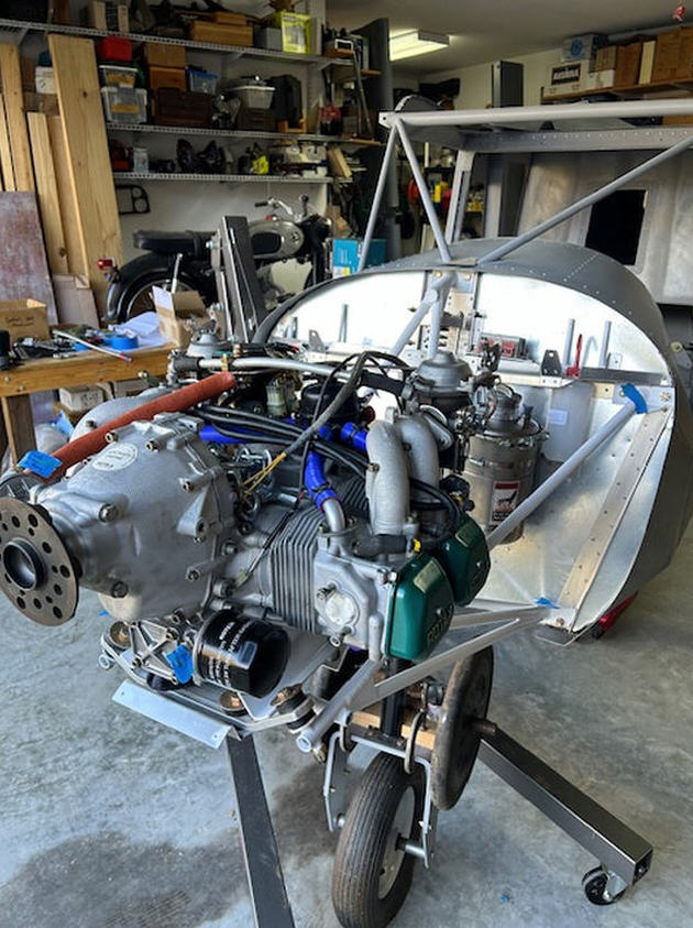
Here is my engine just sitting on the engine bed mount before aligning it and drilling holes for the mounting bolts. I built a special engine table stand at the right height so I was literally able to lift it by hand and set it on the rails. I don’t recommend it and probably won’t do it again but it can be done.
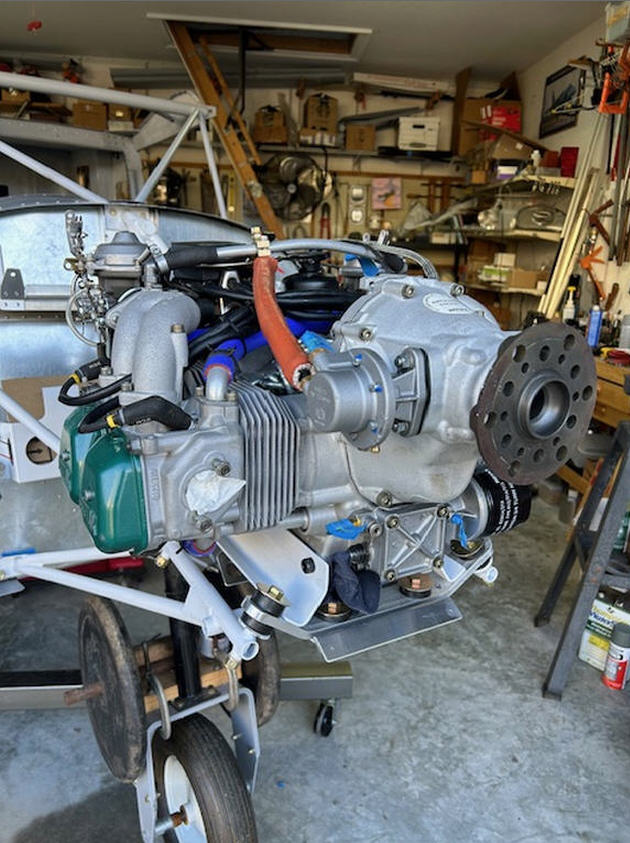
Another picture of the engine from the other side. The 50lb. Weights over the nose gear are there to keep the nose down with the engine removed.
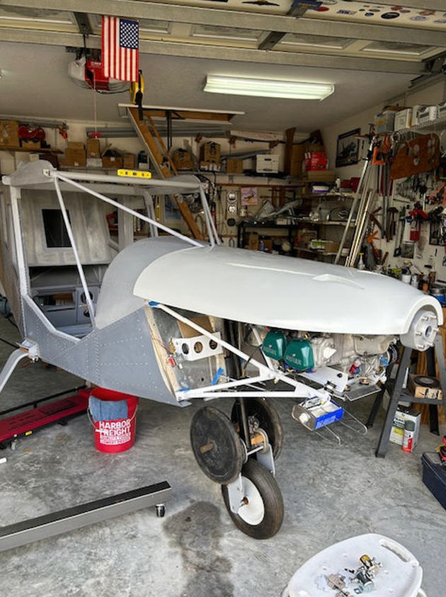
Sometimes it is just fun to set the cowl pieces in place and imagine what the plane will look like. The engine is really light so it is mounted well forward for CG purposes. She will have a long snaz.

This has nothing to do with my airplane but is my oldest grand daughter who thinks I am really smart. She is brilliant.
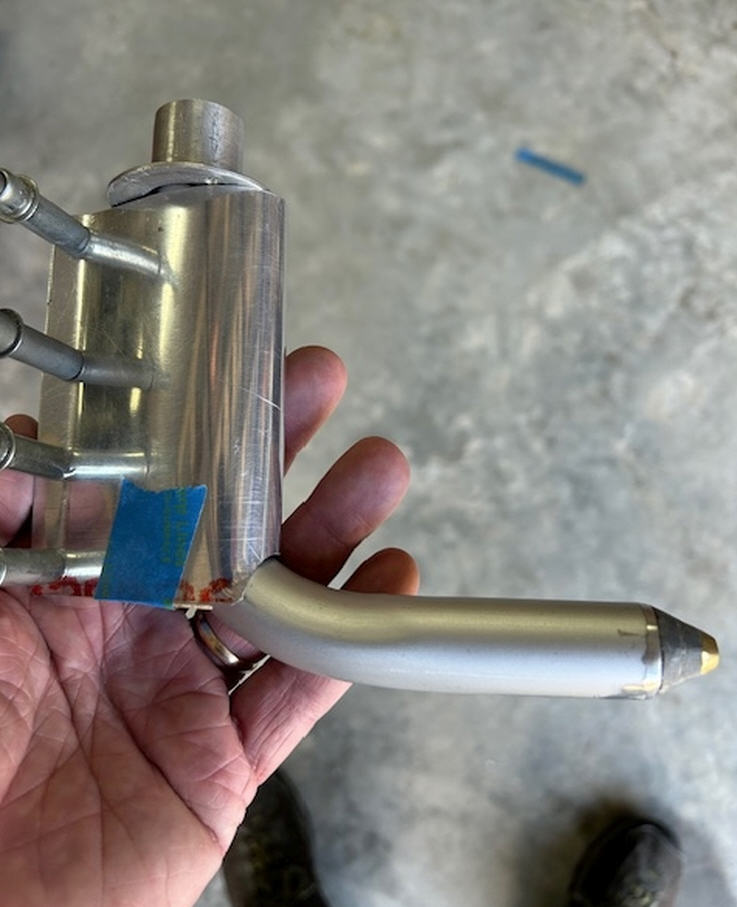
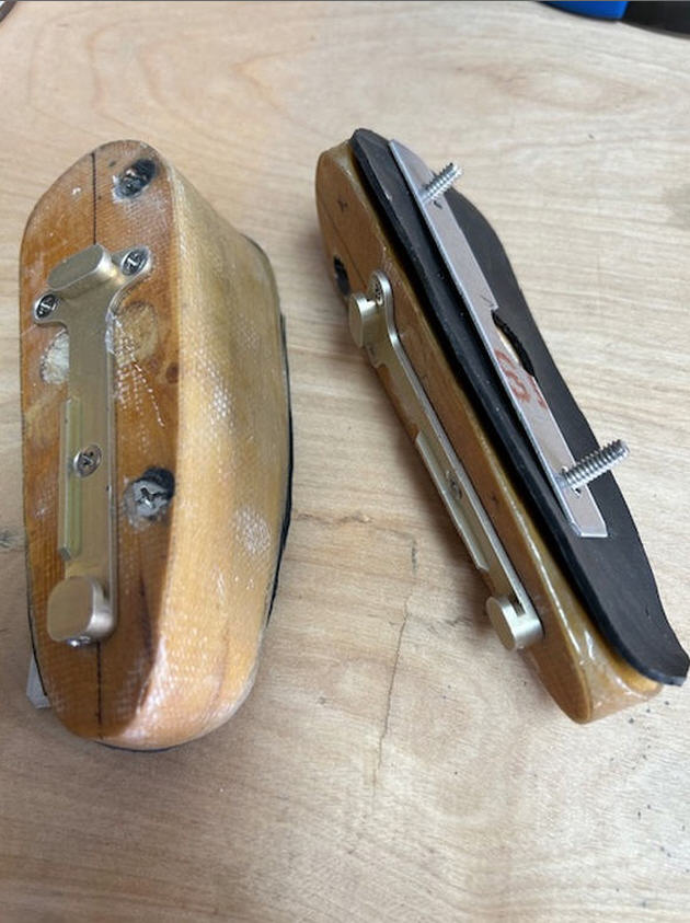
A fellow chapter member talked me into trying to build my own pitot tube with AOA capability. What you are looking at is a section of a shower stool leg, a couple conduit splices, a brass plug and some small 1/8 inch tubing inside. I have about $37 total in it. I have either spent $37 to save $400 (the cost of a AOA probe) or $37 to save $40 (the cost of a non AOA pitot probe). We will see.
More Coming Soon!
![]()